


MS Miayiri DG-206 Ductile Iron Flange Type Globe Valve JIS 20K RF 2.35MPa
Brand:MS Miayiri
Model: DG-206HOT
Size:15A, 20A, 25A, 40A, 50A, 80A, 100A
Connection Specification: JIS20K RF
Main Fluid: LPG (liquid, gas)
Design Pressure: 2.35 MPa
Design Temperature: –5 °C to 120 °C
Pressure Test Pressure: 3.9 MPa
Leak Test Pressure: 2.35 MPa
Body Material: FCD-S

Description
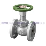
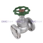
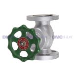
DG-206 Ductile Iron Flange Type Globe Valve
Overview
This valve is primarily manufactured as a shut-off valve for LP gas piping.
Product Name
Product Name: Ductile Iron Flange Type Globe Valve
Model: DG-206
Drawing No.: B-26968-26 (15A–50A), B-26971-06 (80A, 100A)
Sizes
15A, 20A, 25A, 40A, 50A, 80A, 100A
(Note: The nominal size refers to the flange size.)
Application Range
Before installation, confirm the following specifications for use:
(1) Fluid: LPG (liquid, gas)
(2) Design Pressure: 2.35 MPa
(3) Design Temperature: –5 °C to 120 °C
(4) Pressure Test Pressure: 3.9 MPa
(5) Leak Test Pressure: 2.35 MPa
(6) Connection Specification: JIS20K RF
(7) Body Material: FCD-S
Structure and Features
(1) The bonnet is secured by a locknut (bonnet flange for 80A, 100A) and sealed with a gasket.
(2) Valve opening/closing is performed by rotating the handwheel to move the disc up/down. Turning the handwheel clockwise closes the valve; turning counterclockwise opens it.
(3) The gland packing uses a PTFE (polytetrafluoroethylene resin) cone packing, and the seal surface pressure is maintained by a spring washer, providing excellent sealing performance and low handwheel operating force. The gland nut can also be tightened if needed. The upper O‑ring acts as a dust seal.
(4) The disc includes a seat portion and a back‑seat that prevents gland leakage. Both seats employ a soft‑touch design using PTFE packing, ensuring superior sealing.
Handling and Storage
(1) Do not drop, tip over, throw, drag, or otherwise subject the valve to strong impacts, as this may cause leakage or failure.
(2) During handling and storage, keep the valve in its packaging to protect it from dirt, dust, rain, etc.
(3) A flange guard is attached to the packing seat surface of the valve flange. Do not remove it until just before installation to prevent ingress of sand, dirt, etc., which could cause leakage or failure. Be sure to remove it during piping installation.
(4) When lifting the valve, do not lift by the handwheel or suspend it with ropes attached to the handwheel. If the handwheel detaches, it may fall and cause injury or damage.
Piping Instructions
(1) Before installation, thoroughly clean the piping interior and flange surfaces of chips, welding spatter, scale, etc.
(2) The globe valve has a flow direction; confirm the direction indicated on the body and pipe accordingly.
(3) When piping the valve, always remove the flange guard attached to the packing seat surface.
(4) Insert a gasket between the valve flange and the pipe flange in the correct position without misalignment. Apply a suitable sealant to the gasket.
(5) Tighten flange bolts alternately and evenly starting from diagonally opposite bolts to avoid uneven tightening.
(6) Support the valve or piping so that no excessive load is imposed on the piping or mounting parts due to the valve’s weight or operating forces.
(7) Install the valve so that it is not subjected to excessive forces from pipe expansion/contraction, ground settlement, earthquakes, etc.
Precautions for Use
(1) Because a soft seat is used, avoid using a wrench (hanger, etc.) for handwheel operation, as this may cause leakage or failure.
(2) The cone packing used in the gland provides excellent sealing. If leakage occurs, tighten the gland nut. While rotating the handwheel, tighten until the handwheel feels slightly heavier. The gland nut rotation should be about 1/6 to 1/2 turn.
(3) If leakage persists after tightening, if handwheel operation is heavy, or if the gland nut rotation (tightening allowance) is excessive, replace the packing.
Inspection and Maintenance
Perform the following checks at startup, shutdown, and during operation:
(1) Check for leakage from the gland. If leakage is found, tighten the gland nut or replace the cone packing.
(2) Check for leakage from the bonnet. If leakage is found, replace the gasket according to the disassembly/assembly instructions.
(3) If squeaking friction noise is heard during handwheel operation or if operation feels heavy, fully open the valve, clean the packing sliding part of the spindle, apply grease, and operate the handwheel to seat the packing. If not improved, perform disassembly inspection.
(4) If spindle vertical play (backlash) is 0.5–1 mm, wear of the spindle and bonnet threads is suspected. Perform disassembly inspection and replace both spindle and bonnet if wear is found. (Inspection guideline: 5 years or 5,000 cycles.)
Disassembly/Assembly Instructions (Refer to the Structure Diagram)
Disassembly
(1) Set the valve to mid‑opening, purge residual gas, confirm internal pressure is zero, and remove the valve from the piping.
(2) Remove nut “23,” then remove spring washer “22,” nameplate “21,” and handwheel “20.”
(3) After confirming residual gas in the gland is fully vented, loosen gland nut “19.”
(4) Remove locknut “12”; the assembly of spindle “6” and disc “2” will come off together with bonnet “10.” (For 80A, 100A: remove nut “13”; the assembly of spindle “6” and disc “2” will detach together with bonnet “10.”)
(5) Remove gland nut “19” and pull spindle “6” downward while rotating.
(6) Remove internal gland parts: O‑ring “18,” gland “17,” packing gland “15,” packing “14,” and packing seat “13.”
(7) Remove U‑nut “5” and disassemble washer “4” and seat packing “3.”
Assembly
(1) Before assembly, inspect all parts; replace any with harmful corrosion, deformation, scratches, etc., with new ones.
(2) Assembly follows the reverse order of disassembly. Take care to prevent dirt, dust, etc., from entering the valve during work.
(3) Replace packing parts (seat packing “3,” gasket “11,” packing “14,” O‑ring “18”) with new ones.
(4) Do not apply sealant to gasket “11.”
(5) Apply appropriate grease to packing “14” and O‑ring “18.”
(6) Apply appropriate grease to the threaded engagement of spindle “6” and bonnet “10” (for LPG‑resistant thread grease, Permalube JM is recommended).
(7) If thread backlash exceeds 1 mm, wear of the spindle and bonnet threads is suspected. Inspect and replace both spindle and bonnet if wear is found (avoid replacing only the spindle).
(8) When tightening locknut “12” (nut “13” for 80A, 100A), ensure the disc is fully open. Doing so with the valve fully closed may damage the seat or bend the spindle, causing malfunction.
(9) Apply appropriate grease (Permalube JM) to the threaded engagement of the locknut and bonnet to prevent galling.
Recommended tightening torques for locknut “12” (nut “13” for 80A, 100A) are as follows:
| Size | Locknut “12” (N·m) | Nut “13” (N·m) |
|---|---|---|
| 15A | 70–80 | – |
| 20A | 100–120 | – |
| 25A | 140–160 | – |
| 40A | 280–300 | – |
| 50A | 400–450 | – |
| 80A | – | 150–180 |
| 100A | – | 150–180 |
Additional information
| Brand |
MS Miayiri |
|---|
